Cognex Modbus
from https://support.cognex.com/docs/dmst_616SR2/web/EN/Industrial_Protocols_Manual/Content/Topics/PDF/DMCAP/ModbusTCP.htm?TocPath=Industrial%20Network%20Protocols%7C_____4
ModbusTCP
Modbus is an application layer protocol. It provides client/server communication between devices connected to different types of buses or networks. Modbus is a request/response protocol, and its services are specified by using function codes.
Modbus TCP provides the Modbus protocol using TCP/IP. System port 502 is reserved for Modbus communication. It uses standard Ethernet hardware and software to exchange I/O data and diagnostics. DataMan provides Modbus TCP server functionality only.
By default, DataMan has the Modbus TCP protocol disabled. The protocol can be enabled in the Setup Tool, via DMCC, or by scanning a configuration code.
DMCC
The following commands can be used to enable/disable Modbus TCP. The commands can be issued via RS-232 or Telnet connection.
Enable:
||>SET MODBUSTCP.ENABLED ON ||>CONFIG.SAVE ||>REBOOT |
Disable:
||>SET MODBUSTCP.ENABLED OFF ||>CONFIG.SAVE ||>REBOOT |
Reader Configuration Code
Scanning the following reader configuration codes enables/disables Modbus TCP for your corded reader.
Enable:  | Disable:  |
Scanning the following reader configuration codes enables/disables Modbus TCP for your DataMan 8000 base station.
Enable:  | Disable:  |
Setup Tool
Modbus TCP can be enabled by checking Enabled on the Industrial Protocols pane’s Modbus TCP tab. Make sure to save the new selection by choosing “Save Settings” before disconnecting from the reader.
Modbus TCP Handler
Modbus TCP on DataMan is implemented as a server type device. All communication is initiated by the PLC in the form of read and write requests. The PLC acts as a client which actively sends read and write requests.
Getting Started
By default, Modbus TCP is not enabled on the DataMan reader. The protocol must be enabled and the protocol configuration parameters must be set to correctly interact with a PLC. Protocol configuration is accomplished via the DataMan Setup Tool.
In the Setup Tool's Communications application step's Ethernet tab, check Modbus TCP to enable this industrial protocol.
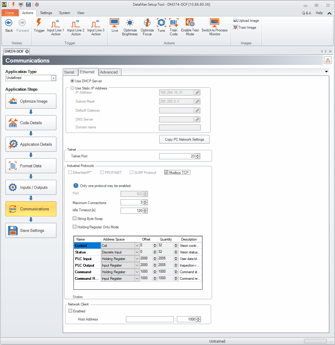
Make sure to save the new selection by clicking the Save Settings button in the upper toolbar before disconnecting from the reader.
Network Configuration
The network configuration defines all the information that the DataMan reader needs to establish a connection with a PLC. In most cases the default values may be used and no changes are need.
| Name | Default | Range | Description |
| Host Port | 502 | Fixed | Port number where Modbus TCP can be accessed on this reader. |
| Max Connections | 3 | 1-6 | Maximum number of simultaneous Modbus TCP connections. |
| Idle Timeout (seconds) | 120 | 1-3600 | Timeout period after which the Modbus TCP connection will be closed. If no traffic is received on a Modbus TCP connection for this amount of time, the connection will automatically be closed. |
| String byte swap | False | True / False | String byte swap enable. If set to True, bytes within each register that forms a string will be swapped. |
| Holding Register Only Mode | False | True / False | Holding Register Only Mode enable. If set to True, all data blocks will be mapped to the Holding Register space. |
Data Block Configuration
The data block configuration defines the data that will be exchanged between the DataMan reader and the PLC. Six data blocks are available. Each block has a predefined function.
DataMan only supports Modbus TCP server operation. For standard server operation, only two configuration options exist. By default the ‘Control’ and ‘Status’ data blocks are located in bit address space (Coil and Discrete Input). If needed, one or both of these data blocks may be redefined to exist in register address space (Holding Register and Input Register). All other data block configurations are fixed.
Standard Block Configuration
| Block Name | Address Space | Offset | Schneider Form Addressing | Quantity |
| Control | Coil or Holding Register | 0 | 000000 – 000031 400000 – 400001 | 32, if coil 2, if holding register |
| Status | Discrete Input or Input Register | 0 | 100000 – 100031 300000 – 300001 | 32, if discrete input 2, if input register |
| PLC Input | Holding Register | 2000 | 402000 – 404004 | 1 – 2005 |
| PLC Output | Input Register | 2000 | 302000 – 304004 | 1 - 2005 |
| Command String | Holding Register | 1000 | 401000 – 401999 | 1 - 1000 |
| Command String Result | Input Register | 1000 | 301000 – 301999 | 1 - 1000 |
DataMan also supports an alternate block configuration. A number of PLCs can only access the ModbusTCP ‘Holding Register’ address space. The alternate 'Holding Register Only' configuration exists to accommodate these PLCs. In this alternate configuration, all reader input and output data is mapped to the ModbusTCP ‘Holding Register’ address space. To enable this alternate mode, perform one of the following options:
- Check the “Holding Register Only” box on the ModbusTCP configuration screen.
- Use the DMCC, which switches on or off the alternate mode (Holding Register Only mode).
Enable:
||>SET MODBUSTCP-HOLDING-ONLY ON |
Disable:
||>SET MODBUSTCP-HOLDING-ONLY OFF |
- scan the Reader Programming Codes
- for the wireless reader
Enable: 
Disable: 
- for the corded reader
Enable: 
Disable: 
Holding Register Only” Block Configuration
| Block Name | Address Space | Offset | Schneider Form Addressing | Quantity |
| Control | Holding Register | 0 | 400000 – 400001 | 2 |
| Status | Holding Register | 5000 | 405000 – 405001 | 2 |
| PLC Input | Holding Register | 2000 | 402000 – 404004 | 1 – 2005 |
| PLC Output | Holding Register | 7000 | 407000 – 409004 | 1 – 2005 |
| Command String | Holding Register | 1000 | 401000 – 401999 | 1 – 1000 |
| Command String Result | Holding Register | 6000 | 406000 – 406999 | 1 – 1000 |
Interface
This section describes the interface to the DataMan reader as seen by the PLC via Modbus TCP. The interface model consists of 6 data blocks grouped in 3 logical pairs:
- Control and Status
- Input Data and Output Data
- String Command and String Response
Control Block
The Control block contains bit type data. This block consists of the control signals sent from the PLC to the reader. It is used by the PLC to initiate actions and acknowledge certain data transfers.
| Bit 7 | Bit 6 | Bit 5 | Bit 4 | Bit 3 | Bit 2 | Bit 1 | Bit 0 |
| Reserved | Results Ack | Buffer Results Enable | Trigger | Trigger Enable | |||
| Bit 15 | Bit 14 | Bit 13 | Bit 12 | Bit 11 | Bit 10 | Bit 9 | Bit 8 |
| Reserved | |||||||
| Bit 23 | Bit 22 | Bit 21 | Bit 20 | Bit 19 | Bit 18 | Bit 17 | Bit 16 |
| Reserved | Initiate String Cmd | Set User Data | |||||
| Bit 31 | Bit 30 | Bit 29 | Bit 28 | Bit 27 | Bit 26 | Bit 25 | Bit 24 |
| SoftEvent 7 | SoftEvent 6 | SoftEvent 5 | SoftEvent 4 | SoftEvent 3 | SoftEvent 2 | SoftEvent 1 | SoftEvent 0 |
Control Block Field Descriptions
| Bit | Name | Description |
| 0 | Trigger Enable | This field is set to enable triggering via the Trigger bit. Clear this field to disable the network triggering mechanism. |
| 1 | Trigger | Setting this bit triggers an acquisition. Note that the Trigger Ready bit must be set high before triggering an acquisition. |
| 2 | Buffer Results Enable | When this bit is set, each read result (ResultID, ResultCode, ResultLength and ResultData fields) will be held in the Output Block until it is acknowledged. Once acknowledged, the next set of read results will be made available from the buffer. If new read results arrive before the earlier set is acknowledged the new set will be queued in the reader’s buffer. Up to 6 read results can be held in the reader’s buffer. Refer to section Operation for a description of the acknowledgement handshake sequence. |
| 3 | ResultsAck | Set by the PLC to acknowledge that it has received the latest results (ResultID, ResultCode, ResultLength and ResultData fields). When the reader sees this bit transition from 0à1 it clears the ResultsAvailable bit. This forms a logical handshake between the PLC and reader. If result buffering is enabled, the acknowledgement will cause the next set of queued results to be moved from the buffer. See section Operation for a description of the acknowledgement handshake sequence. |
| 4-15 | Reserved | Future use |
| 16 | SetUserData | Set by the PLC to signal that new UserData is available. After reading the new UserData the reader sets SetUserDataAck to signal that the transfer is complete. This forms a logical handshake between the PLC and reader. |
| 17 | Initiate StringCmd | Set by the PLC to signal that a new StringCommand is available. After processing the command, the reader sets StringCmdAck to signal that the command result is available. This forms a logical handshake between the PLC and reader. |
| 18-23 | Reserved | Future use |
| 24-31 | SoftEvents | Bits act as virtual discrete inputs. When a bit transitions from 0 -> 1 the associated action is executed. After executing the action the reader sets the corresponding SoftEventAck to signal that the action is complete. This forms a logical handshake between the PLC and reader. Bit0: Train code Bit1: Train match string Bit2: Train focus Bit3: Train brightness Bit4: Un-Train Bit5: Reserved (future use) Bit6: Execute DMCC command Bit7: Set match string |
Status Block
The status block contains bit type data. This block consists of the status signals sent from the reader to the PLC. It is used by the reader to signal status and handshake certain data transfers.
| Bit 7 | Bit 6 | Bit 5 | Bit 4 | Bit 3 | Bit 2 | Bit 1 | Bit 0 |
| Reserved | Missed Acq | Acquiring | Trigger Ack | Trigger Ready | |||
| Bit 15 | Bit 14 | Bit 13 | Bit 12 | Bit 11 | Bit 10 | Bit 9 | Bit 8 |
General Fault | Reserved | Results Available | Results Buffer Overrun | Decode Complete Toggle | Decoding | ||
| Bit 23 | Bit 22 | Bit 21 | Bit 20 | Bit 19 | Bit 18 | Bit 17 | Bit 16 |
| Reserved | String Cmd Ack | Set User Data Ack | |||||
| Bit 31 | Bit 30 | Bit 29 | Bit 28 | Bit 27 | Bit 26 | Bit 25 | Bit 24 |
SoftEvent Ack 7 | SoftEvent Ack 6 | SoftEvent Ack 5 | SoftEvent Ack 4 | SoftEvent Ack3 | SoftEvent Ack 2 | SoftEvent Ack 1 | SoftEvent Ack 0 |
Status Block Field Descriptions
| Bit | Name | Description |
| 0 | Trigger Ready | Indicates when the reader is ready to accept a new Trigger. The reader sets this bit when TriggerEnable has been set and the reader is ready to accept a new trigger. |
| 1 | TriggerAck | Indicates when the reader recognizes that Trigger has been set. This bit will remain set until the Trigger bit has been cleared. |
| 2 | Acquiring | Set to indicate that the reader is in the process of acquiring an image.
|
| 3 | Missed Acq | Indicates that the reader missed a requested acquisition trigger. The bit is cleared when the next acquisition is issued. |
| 4-7 | Reserved | Future use |
| 8 | Decoding | Set to indicate that the reader is in the process of decoding an image. |
| 9 | Decode Complete Toggle | Indicates new result data is available. Bit toggles state (0 -> 1 or 1 -> 0) each time new result data becomes available. |
| 10 | Results Buffer Overrun | Set to indicate that the reader has discarded a set of read results because the PLC has not acknowledged the earlier results. Cleared when the next set of result data is successfully queued in the buffer. This bit only has meaning if result buffering is enabled. |
| 11 | Results Available | Set to indicate that new result data is available. Bit will remain set until acknowledged with ResultsAck even if additional new read results become available. |
| 12-14 | Reserved | Future use |
| 15 | General Fault | Set to indicate that an Ethernet communications fault has occurred. Currently only used by SoftEvent operations. Bit will remain set until the next successful SoftEvent or until TriggerEnable is set low and then high again. |
| 16 | Set User Data Ack | Set to indicate that the reader has received new UserData. Bit will remain set until the corresponding SetUserData bit is cleared. This forms a logical handshake between the PLC and reader. |
| 17 | String Cmd Ack | Set to indicate that the reader has completed processing the latest string command and that the command response is available. Bit will remain set until the corresponding InitiateStringCmd bit is cleared. This forms a logical handshake between the PLC and reader. |
| 18-23 | Reserved | Future use |
| 24-31 | SoftEvent Ack | Set to indicate that the reader has completed the SoftEvent action. Bit will remain set until the corresponding SoftEvent bit is cleared. This forms a logical handshake between the PLC and reader. Bit0: Ack train code Bit1: Ack train match string Bit2: Ack train focus Bit3: Ack train brightness Bit4: Ack untrain Bit5: Reserved (future use) Bit6: Ack Execute DMCC command Bit7: Ack set match string |
Input Data Block
The Input Data block is sent from the PLC to the reader. The block consists of user defined data that may be used as input to the acquisition/decode operation.
| Word 0 | Word 1 | Word 2..N |
| Reserved | User Data Length | User Data |
Input Data Block Field Descriptions
| Word | Name | Description |
| 0 | Reserved | Future use |
| 1 | User Data Length | Number of bytes of valid data actually contained in the UserData field. |
| 2..N | User Data | User defined data that may be used as an input to the acquisition/decode. |
Output Data Block
The Output Data block is sent from the reader to the PLC. The block consists primarily of read result data.
| Word 0 | Word 1 | Word 2 | Word 3 | Word 4 | Word 5...n |
| Reserved | Trigger ID | Result ID | Result Code | Result Length | Result Data |
Output Data Block Field Descriptions
| Word | Name | Description |
| 0 | Reserved | Future use |
| 1 | Trigger ID | Trigger identifier. Identifier of the next trigger to be issued. Used to match issued triggers with result data that is received later. This same value will be returned as the ResultID of the corresponding read. |
| 2 | Result ID | Result identifier. This is the value of TriggerID when the corresponding trigger was issued. Used to match up triggers with corresponding result data. |
| 3 | Result Code | Indicates the success or failure of the read that produced this result set. Bit0: 1=Read, 0=No read Bit1: 1=Validated, 0=Not Validated Bit2: 1=Verified, 0=Not Verified Bit3: 1=Acquisition trigger overrun Bit4: 1=Acquisition buffer overrun Bit5-15: Reserved (future use) |
| 4 | Result Data Length | Number of bytes of valid data actually in the ResultData field. |
| 5...n | Result Data | Result data from this acquisition/decode. Formatted as ASCII text with two characters per 16-bit register. No terminating null character. |
String Command Block
The String Command block is sent from the PLC to the reader. The block is used to transport string based commands (DMCC) to the reader.
| Word 0 | Word 1...n |
| Length | String Command |
String Command Block Field Descriptions
| Word | Name | Description |
| 0 | Length | Number of bytes of valid data in the StringCommand field. |
| 1..N | String Command | ASCII text string containing the command to execute. No null termination required. |
String Command Result Block
The String Command Result block is sent from the reader to the PLC. The block is used to transport the response from string based commands (DMCC) to the PLC.
| Word 0 | Word 1 | Word 2..N |
Result Code | Length | String Command Result |
String Command Result Block Field Descriptions
| Word | Name | Description |
| 0 | Result Code | Code value indicating the success or failure of the command. Refer to the Command Reference, available through the Windows Start menu or the DataMan Setup Tool Help menu, for specific values. |
| 1 | Length | Number of bytes of valid data in the StringCommand field. |
| 2..N | String Command Result | ASCII text string containing the command to execute. No null termination required. |
Operation
Modbus TCP is a request/response based protocol. All communications are originated from the PLC. The reader acts as server.
Requests
To initiate actions or control data transfer, the PLC changes the state of certain bits of the Control block and sends requests to the reader.
After each request, the reader will process changes in state of the bits in the Control block. Some state changes require additional communications with the PLC, such as writing updated acknowledge bit values or reading a new string command. These additional communications are handled automatically by the reader. Other state changes initiate activities such as triggering a read or executing a SoftEvent. The reader performs the requested action and later reports the results.
Typical Sequence Diagram

Handshaking
A number of actions are accomplished by means of a logical handshake between the reader and the PLC (triggering, transferring results, executing SoftEvents, string commands, and so on). This is done to ensure that both sides of a transaction know the state of the operation on the opposite side. Network transmission delays will always introduce a finite time delay in transfer data and signals. Without this handshaking, it is possible that one side of a transaction might not detect a signal state change on the other side. Any operation that has both an initiating signal and corresponding acknowledge signal will use this basic handshake procedure.
The procedure involves a four-way handshake.
- Assert signal
- Signal acknowledge
- De-assert signal
- De-assert acknowledge
The requesting device asserts the signal to request an action (set bit 0 -> 1). When the target device detects the signal and the requested operation has completed, it asserts the corresponding acknowledge (set bit 0 -> 1). When the requesting device detects the acknowledge, it de-asserts the original signal (1 -> 0). Finally, when the target device detects the original signal de-asserted, it de-asserts its acknowledge (bit 0 -> 1). To function correctly both sides must see the complete assert/de-assert cycle (0 -> 1 and 1 -> 0). The requesting device should not initiate a subsequent request until the cycle completes.
Acquisition Sequence
DataMan can be triggered to acquire images by several methods. It can be done by setting the Trigger bit or issuing a trigger String Command. It can also be done via DMCC command (Telnet) or hardwired trigger signal. The Trigger bit method will be discussed here.
On startup, TriggerEnable will be False. It must be set to True to enable triggering via the Trigger bit. When the device is ready to accept triggers, the reader will set the TriggerReady bit to True.
While the TriggerReady bit is True, each time the reader detects the Trigger bit change from 0 -> 1, it will initiate a read. The Trigger bit should be held in the new state until that same state value is seen in the TriggerAck bit (this is a necessary handshake to guarantee that the trigger is seen by the reader).
During an acquisition, the TriggerReady bit will be cleared and the Acquiring bit will be set to True. When the acquisition is completed, the Acquiring bit will be cleared. When the device is ready to begin another image acquisition, the TriggerReady bit will again be set to True.
If results buffering is enabled, the reader will allow overlapped acquisition and decoding operations. TriggerReady will be set high after acquisition is complete but while decoding is still in process. This can be used to achieve faster overall trigger rates. If result buffering is not enabled, the TriggerReady bit will remain low until both the acquisition and decode operations have completed.

To force a reset of the trigger mechanism set the TriggerEnable to False until TriggerReady is also set to False. Then, TriggerEnable can be set to True to re-enable acquisition.
As a special case, an acquisition can be cancelled by clearing the Trigger signal before the read operation has completed. This allows for the cancellation of reads in Presentation and Manual mode if no code is in the field of view. To ensure that a read is not unintentionally cancelled, it is advised that the PLC hold the Trigger signal True until both TriggerAck and ResultsAvailable are True (or DecodeComplete toggles state).
Decode / Result Sequence
After an image is acquired, it is decoded. While being decoded, the Decoding bit is set. When the decode operation has completed, the Decoding bit is cleared. The ResultsBufferEnable determines how decode results are handled by the reader.
If ResultsBufferEnable is set to False, then the read results are immediately placed into the Output Data block, ResultsAvailable is set to True and DecodeComplete is toggled.
If ResultsBufferEnable is set to True, the new results are queued in a buffer and DecodeComplete is toggled. The earlier read results remain in the Output Data block until they are acknowledged by the PLC. After the acknowledgment handshake, if there are more results in the queue, the next set of results will be placed in the Output Data block and ResultsAvailable is set to True.

Results Buffering
There is an option to enable a queue for read results. If enabled, this allows a finite number of sets of result data to be queued up until the PLC has time to read them. This is useful to smooth out data flow if the PLC slows down for short periods of time.
Also, if result buffering is enabled the reader will allow overlapped acquisition and decode operations. Depending on the application this can be used to achieve faster overall trigger rates. See the Acquisition Sequence description for further details.
In general, if reads are occurring faster than results can be transferred to the PLC, some data will be lost. The primary difference between buffering or not buffering determines which results get discarded. If buffering is not enabled, the most recent results are kept and the earlier result (which was not read by the PLC quickly enough) is lost. The more recent result will overwrite the earlier result. If buffering is enabled (and the queue becomes full) the most recent results are discarded until room becomes available in the results queue.
SoftEvents
SoftEvents act as virtual inputs. When the value of a SoftEvent bit changes from 0 to 1, the action associated with the event is executed. When the action completes, the corresponding SoftEventAck bit changes from 0 to 1 to signal completion.
The SoftEvent and SoftEventAck form a logical handshake. After SoftEventAck changes to 1, make sure that the original SoftEvent is set back to 0. When that occurs, SoftEventAck is automatically set back to 0.
The “ExecuteDMCC” and “SetMatchString” SoftEvent actions require user supplied data. Make sure that this data is written to the UserData and UserDataLength area of the Input Data block prior to invoking the SoftEvent. Only one SoftEvent can be invoked at a time, because both of these SoftEvents depend on the UserData.
String Commands
The DataMan Modbus TCP Protocol implementation includes a String Command feature. This feature allows you to execute string-based DMCCs. The DMCC is sent to the reader through the String Command block. The DMCC result is returned through the String Command Result block. Initiating a command and notification of completion is accomplished by signaling bits in the Control and Status blocks.
To execute a DMCC, the command string is placed in the data field of the String Command block. The command string consists of standard ASCII text. The same command format is used for a serial (RS-232) or Telnet connection. The string does not need to be terminated with a null character. Instead, the length of the string, that is, the number of ASCII characters, is placed in the length field of the String Command block.
After executing the DMCC, the result string is returned in the String Command Result block. Similar to the original command, the result string consists of ASCII characters in the same format as returned through a serial or Telnet connection. Also, there is no terminating null character. Instead, the length of the result is returned in the Command String Result length field. The Command String Result block also contains a numeric result code. This allows you to determine the success or failure of the command without having to parse the text string. The values of the result code are defined in the DMCC documentation, available through the Windows Start menu or the Setup Tool Help menu.
General Fault Indicator
When a communication-related fault occurs, the “GeneralFault” bit changes from 0 to 1. The only fault conditions supported are SoftEvent operations. If a SoftEvent operation fails, the fault bit will be set. The fault bit will remain set until the next successful SoftEvent operation, or until TriggerEnable is set to 0 and then back to 1.

Examples
Included with the DataMan Setup Tool installer are two example PLC programs created with CoDeSys v2.3 software. These samples are designed and tested on a Wago 750-841 PLC. These programs demonstrate the DataMan ID readers’ capabilities and proper operation. You can do the same operations by using more advanced features and efficient programming practices with Wago PLCs. The examples try to show different approaches in the techniques used for the communication to the DataMan reader and they are better for demonstration purposes.
ApplicationLayer Example
This sample realizes a generic data transfer between the DataMan reader and the PLC. Memory areas of the “Control”, “Status” and “Output Area” are cloned in the PLC and synchronized cyclically, or as needed. Each data area is synchronized with its own instance of “ETHERNETMODBUSMASTER_TCP”. This causes three TCP connections to be open simultaneously. Make sure that the Modbus TCP related setting “Maximum Connections” on the DataMan reader is set to at least 3 for this example to work.
Function
The example application demonstrates the following operations:
- Transfer the 32-bit “Control” register data from the PLC to the reader.
- Transfer the 32-bit “Status” register data from the reader to the PLC.
- Transfer “Output Data” from the reader to the PLC.
All actions are started when there is a connection to the reader.
Transferring “Control” Register Data
All data gets transferred when there is a change in the local PLC data. The local PLC data can be manipulated in the visualization.
Transferring Status Register Data
All data gets transferred cyclically. The poll interval can be specified in the visualization.
Transferring Output Data
All data gets transferred cyclically. The poll interval can be specified in the visualization.
DataManControl Example
This sample shows in a sequential manner the steps to do to achieve one of the functions named in the following subsection. To outline this chronological sequence, “Sequential Function Chart” is used as programming language.
Function
The example application demonstrates the following operations:
- Triggering a read
- Getting read results
- Executing string commands (DMCC)
- Executing SoftEvent operations
- Train code
- Train match string
- Train focus
- Train brightness
- Untrain
- Execute DMCC
- Set match string
The “Main” program contains variables to invoke each of these operations. The operation is invoked by toggling the control bool directly or from the visualization (red=0, green=1) from 0 to 1. This will invoke the associated subroutine to perform the operation. When the operation 4 is complete, the subroutine will set the control bit back to 0.
Triggering a Read
The example provides a “Continuous Trigger”. As the name implies, enabling the “xTrigger” bit will invoke a continuous series of read operations. Once enabled, the “xTrigger” control bit will remain set until you disable it.
Primarily, the trigger subroutine manages the trigger handshake operation between the PLC and the reader. The control Result Ack and Trigger bits are reset, the Trigger Enable bit is set, the PLC waits for the corresponding TriggerReady status bit from the reader, and the control Trigger bit is set. Refer to a description of handshaking in section Operation.
Getting Read Results
For this example the operation of triggering a read and getting read results was intentionally separated. This is to support the situation where the PLC is not the source of the read trigger. For example, the reader may be configured to use a hardware trigger. In such a case, only the get results subroutine would be needed.
Like the triggering subroutine, the get results subroutine manages the results handshake operation between the PLC and the reader. The routine waits for the ResultsAvailable status bit to become active, it copies the result data to internal storage, and then executes the ResultsAck handshake. Refer to a description of handshaking in section Operation.
The read result consists of a ResultCode, ResultLength, and ResultData. Refer to section Output Data Block Field Descriptions for details of the ResultCode values. The ResultLength field indicates how many bytes of actual result data exist in the ResultData field. The subroutine converts this byte length to word length before copying the results to internal storage.
Execute String Commands (DMCC)
The string command feature provides a simple way to invoke DMCCs from the PLC. The command format and command result format is exactly identical to that used for serial or Telnet DMCC operation.
This subroutine copies an example DMCC (||>GET DEVICE.TYPE) to the String Command block and then manages the string command handshake operation between the PLC and the reader to invoke the command and retrieve the command result. Any valid DMCC command may be invoked with this mechanism. Refer to the DataMan Command Reference document available through the Windows Start menu or the Setup Tool Help menu.
Execute SoftEvents
SoftEvents are used to invoke a predefined action. Each SoftEvent is essentially a virtual input signal. Each of the SoftEvent subroutines manages the handshake operation between the PLC and the reader to invoke the predefined action. The associated action is invoked when the SoftEvent bit toggles from 0 to 1. The subroutine then watches for the associated SoftEventAck bit from the reader which signals that the action is complete. For a description of handshaking, see section Operation.
Modbus Client and Server Devices
Modbus communication systems use Client and Server devices. (also called masters and slaves in other terminology). These clients and servers are represented as Devices in Cognex Designer.

Usually, Modbus Server Devices are measurement devices that measure and store data. On the other hand, Modbus Client Devices are usually supervisory systems used to monitor and control the Modbus Server devices. Modbus Client Devices periodically read (poll) and/or write data on the Modbus Server Devices: as such, communication is always initiated by a Modbus Client Device. It sends commands (Modbus Functions) to a Modbus Server Device which then sends back data as response.
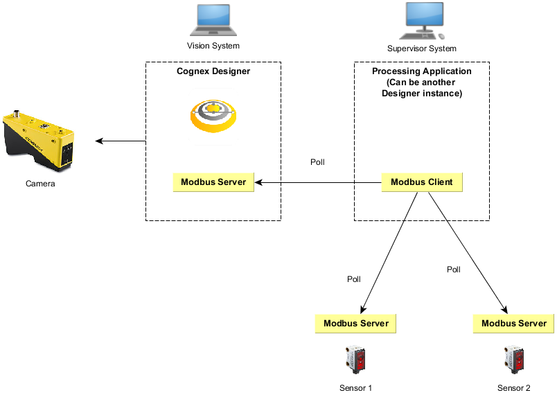
The example below illustrates a deployment where Cognex Designer acts as the Modbus Server . In this case, Cognex Designer runs as a vision system that measures data and provides the measured result to another system (that can be another installation of Cognex Designer).
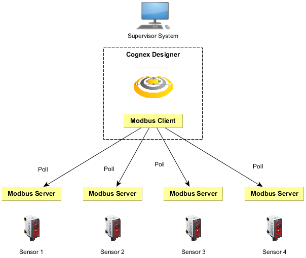
The example below illustrates a deployment where Cognex Designer acts as the Modbus Client. In this case, Cognex Designer is used to communicate with remote servers to acquire sensor data. Cognex Designer runs on a supervisor computer that periodically polls the sensors and processes and visualizes the data.
The Modbus TCP frame format used is as follows:
| Name | Length (bytes) | Description |
| Transaction ID | 2 | Used for synchronization between Client and Server messages. |
| Protocol ID | 2 | The value is zero for Modbus TCP. |
| Length field | 2 | The number of remaining bytes in the frame. |
| Unit identifier | 1 | Specifies the server address. The value is 255 if not used. |
| Function code | 1 | The function code that represents the Modbus operation (e.g. Read Coils = 1, Read Discrete Inputs = 2) |
| Data bytes | n | Data as response or commands, containing the address. |
The first four items are the communication overhead of the frame, while the last two items in bold are the payload of the message frame.
from https://www.universal-robots.com/articles/ur/application-installation/using-a-barcode-reader-directly-with-the-robot/
USING A BARCODE READER DIRECTLY WITH THE ROBOT
This article describes how to connect a Modbus enabled barcode reader, and use it in a program.
Examples are valid for:
CB3 Software version: 3.2.18744
This how to uses a barcode to move to different positions, based on what barcode is read. This can e.g. be used to do different subprograms based on what object the robot is working with, or to pick or place different objects differently.
This example uses a Cognex Dataman 260 barcode reader. Barcode readers with similar communication capabilities might work similarly.
Examples have been made using Cognex' software DataMan Setup Tool 5.6.0 SR1.
Note that other makes of barcode readers may behave differently and may not work directly with UR robots.
The target is to move to different positions, depending on what barcode is read.
The example is split into two sections:
- Barcode reader is auto-triggered, robot waits for new data
- Barcode reader is trigged by the robot, robot confirms new data
SETTING UP THE BARCODE READER
Always consult the documentation provided by the vendor of the barcode reader.
Below is only a brief explanation of the settings used for below examples.
- Setup the barcode reader to have a static IP-address, and be on the same subnet, as the robot.
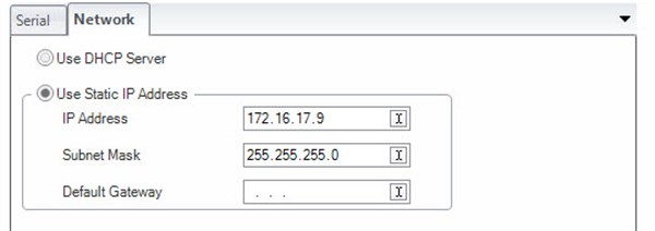
(Image from Dataman Setup Tool 5.6)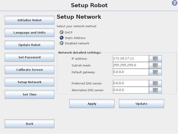
- Setup the barcode reader to communicate over Modbus TCP.
Settings below are not crucial, and other might be used.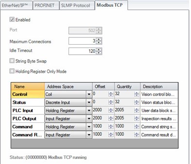
(Image from Dataman Setup Tool 5.6)
According to Cognex' Communications and Programming Guide, the barcode reader and robot can communicate over Modbus TCP, using the Control (bit) register, Status (bit) register and Output data registers (integers). Other registers may be used depending on barcode reader and complexity of application.
SETTING UP THE ROBOT (INSTALLATION)
Setting up Modbus channels are covered in this article.
The following modbus channels are relevant for below example:
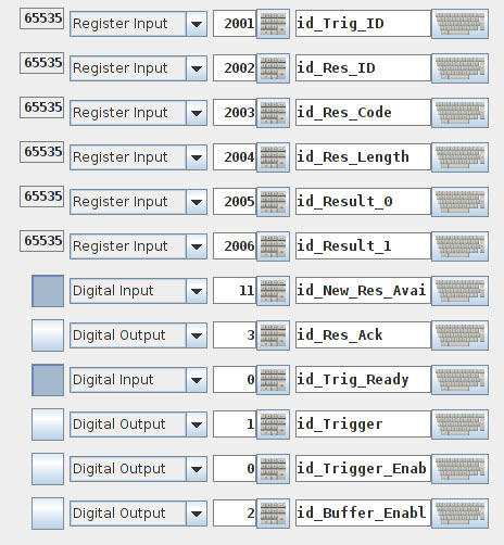
| Address | Type | Name | Explanation |
| 2001 | Register input | Trig_ID | ID no. of next data to be read. |
| 2002 | Register input | Res_ID | ID no. of last data read |
| 2003 | Register input | Res_Code | Indicator of the success of the read. |
| 2004 | Register input | Res_Length | Length of the reault in bytes (ASCII chars) |
| 2005 | Register input | Result_0 | First and second ASCII char |
| 2006 | Register input | Result_1 | Third and fourth ASCII-char |
| 2007+ | Register input | Result (2-N) | More ASCII chars |
| 0 | Digital Output | Trigger_Enable | Set high to enable triggering with below output. |
| 1 | Digital Output | Trigger | Set high to trigger barcode reader. |
| 2 | Digital Output | Buffer_Enable | High = buffering of results enabled. Low = no buffer. Consult documentation. |
| 3 | Digital Output | Res_Ack | Acknowledge that the result have been read. Clears "New_Res_Available". |
| 0 | Digital Input | Trig_Ready | High = trigger is ready. Low = trigger not ready or disabled. |
| 11 | Digital Input | New_Res_Available | High if a new result is available. |
Addresses are subject to change, by the offset defined in the Modbus TCP setup of the barcode reader defined in above section.
The result from the barcode reader is formattet as an ASCII string.
See ASCII-values at following link: www.asciitable.com
Result is outputtet into MODBUS registers. These can contain 16-bit integers, as ASCII chars are only 8 bits, two chars can be stored in each register channel.
Examples of barcodes:
| Barcode (QR) | ASCII-string | Register outputs |
 | "1" | Res_Length = 1 |
 | "2" | Res_Length = 1 Result_0 = 50 |
 | "UR3" | Res_Length = 3 Result_0 = 21077 = "UR" Result_0_low_byte = 85 = "U" Result_0_high_byte = 82 = "R" Result_1 = 51 = "3" |
 | "UR5" | Res_Length = 3 Result_0 = 21077 = "UR" Result_1 = 53 = "5" |
| | "UR10" | Res_Length = 4 |
AUTOTRIGGERING
This section covers how to use the barcode reader with the robot, when the barcode is automatically taking new scans within a given time.
First setup the barcode reader to automatically scan for new barcodes, and send the result over Modbus TCP.
Consult documentation provided by vendor of barcode reader.
In the robot program, start out by saving the "Res_ID" value to a local variable "last_barcode_id".
Wait for the barcode reader to increment "Res_ID" to a value higher than the last value.
Thus we know that a new barcode is read and stored.
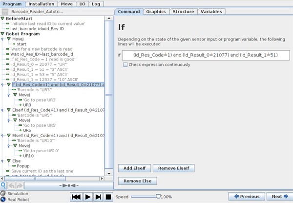
Based on what barcode is read, either "UR3", "UR5" and "UR10" the robot shall move to three different positions.
In the if-statement, we have three statements:
Res_Code = 1, thus the read is good
AND
Result_0 = 21077, thus first two chars are "UR"
AND
Result_1 is either 51 ("3"), 53 ("5") or 12337 ("10").
If all these statements are true, the robot will move to either positions UR3, UR5 or UR10.
If none of the statements are true, thus we have read a barcode that is not equal to the above mentioned or the read is bad, thus we create a popup, to inform the user of the false barcode.
After the sequence, we save the current result ID to our "last_barcode_id" variable.
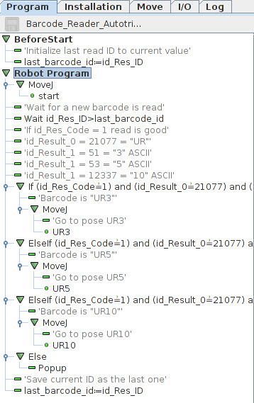
See attached program "Barcode_Reader_Autotrigger.urp" and "default.installation".
BARCODE READER TRIGGERED BY ROBOT
This section covers how to have the robot trigger the barcode reader, to scan a new available barcode.
First, setup the barcode reader to wait for a trigger-signal to scan a new barcode, and send the result over Modbus TCP.
Consult documentation provided by vendor of barcode reader.
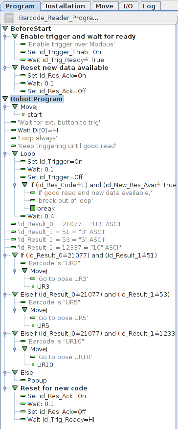
In the program BeforeStart sequence, we set the Trigger_Enable bit high, to allow us to trigger the barcode reader over Modbus.
Afterwards we wait for the Trig_Ready to be high, thus the barcode reader confirms that we can trig over Modbus.
Thereafter we clear the current value stored in the result, by setting Res_Ack to high, to confirm current data is received.
In the Robot Program, we first wait for an external signal, that a new item is ready for scan.
This could be an external sensor, telling the robot that a new item is in front of the barcode reader.
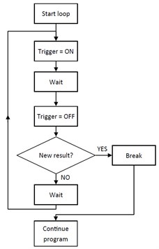
When we want to scan for a new barcode, a loop is made.
The Loop-command is set up to loop continously.
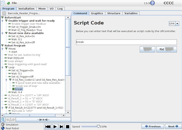
First we set the Trigger bit high, to trigger the barcode reader, we wait for a short delay, and thus set the Trigger bit back to off.
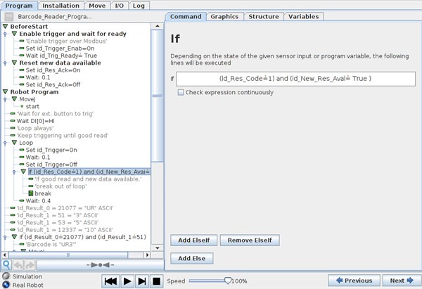
After the trigger, we use an If-statement to test the Res_Code = 1, thus we have a good read AND that New_Res_Available = True, so new data is stored. If both statements are true, we issue the "break" script command. This command will break out of the "Loop".
If no good read is made, the loop will make the barcode reader try again until a good read is confirmed.
This section is not strictly necessary, but provides confirmation, that a new code is actually read.
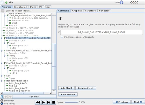
Based on what barcode is read, either "UR3", "UR5" and "UR10" the robot shall move to three different positions.
In the if-statement, we have two statements:
Result_0 = 21077, thus first two chars are "UR"
AND
Result_1 is either 51 ("3"), 53 ("5") or 12337 ("10").
If all these statements are true, the robot will move to either positions UR3, UR5 or UR10.
If none of the statements are true, thus we have read a barcode that is not equal to the above mentioned or the read is bad, thus we create a popup, to inform the user of the false barcode.
After the sequence, we clear the result, by setting Res_Ack to high, to confirm the data is read.
And if necessary wait for the Trig_Ready to be high, so we are sure the barcode reader is ready to scan again.
See attached program "Barcode_Reader_Programtrigger.urp" and "default.installation".


留言
張貼留言