MX1508 直流馬達步進馬達驅動模組
from https://github.com/Saeterncj/MX1508
MX1508
Arduino library for MX1508 dual DC motor driver
This motor driver is only ideal for low power applications(Motors that draws less that 1.5A).
The datasheet for MX1508 in chinese can be found here: https://bit.ly/2k7lxLm
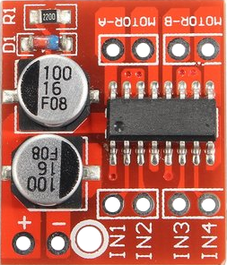
Specifications
- Module Supply Voltage: DC 2-10V
- Signal input voltage: DC 1.8-7V
- Single working current: 1.5A
- Peak current up to 2.5A
- Low standby current (less than 0.1uA)
- Built-in common conduction circuit, the input terminal vacant, the motor does not malfunction
- Size: 24.7 x 21 x 7mm
- Mounting hole diameter: 2 mm
Objective
This library is made to simplify the use of MX1508. This Arduino Libary only requires a few lines of code to start controlling DC motors with mx1508. Here is a sample code of spinning a DC motor with a value of PWM = 100.
#include <MX1508.h>#define PINA 9 #define PINB 10 #define NUMPWM 2 #define PWM 100/* * MX1508(uint8_t pinIN1, uint8_t pinIN2, DecayMode decayMode, NumOfPwmPins numPWM); * DecayMode must be FAST_DECAY or SLOW_DECAY, * NumOfPwmPins, either use 1 or 2 pwm. * I recommend using 2 pwm pins per motor so spinning motor forward and backward gives similar response. * if using 1 pwm pin, make sure its pinIN1, then set pinIN2 to any digital pin. I dont recommend this setting because * we need to use FAST_DECAY in one direction and SLOW_DECAY for the other direction. */MX1508 motorA(PINA,PINB, FAST_DECAY, NUMPWM);void setup() {} void loop() {motorA.motorGo(PWM);}
Details
An example of this library in action can be seen here: https://www.youtube.com/watch?v=jntVTbv9dD0&t=196s
The video shows the responses we get from a DC motor by sweeping pwm from -200 -> 200. The red line shows the pwm and the blue line represents the angular speed of the DC motor. The video show different speed responses by changing the parameters of our class MX1508.
Decay mode is just how fast or slow the motor's coil current decay to zero. The first mode we set is SLOW_DECAY w/ both pins using PWM pins. The response shows a much more linear response for CW and CWW rotation. The second mode, we set the decay mode to FAST_DECAY and we can see that the response is much more logarithmic/aggresive response. Slow_DECAY = linear response, looks like a 'V'. FAST_DECAY = aggresive response, looks like a 'U'.
I see online that one of the main disadvantage of this motor driver is the requirement of PWM pins. It requires 2 pwm pin per 1 motor. However, the 2nd half of the video show that it is possible to use just only one PWM and any digital pin instead of using 2 different PWM pins. There is a huge tradeoff for this tho. The response you get from the motor turning one direction is different than the response you get from turning the other direction. In one way, you will get a FAST_DECAY response, and then SlOW_DECAY response on the other. This should only be use if you have absolutely no more PWM pins.
Methods and Functions
- motorGo(pwmVal)
- This sets the PWM val(
speed).
- This sets the PWM val(
- stopMotor()
- Simply stops the motor
- setResolution(pwmResolution)
- It is possible to change the resolution of pwm. To be able to use this feature, You must use pwm pins of 9 and 10 of arduino nano/uno to utulize the 16bit PWM. Theoretically, the value can be anywhere from 0 - 65535)
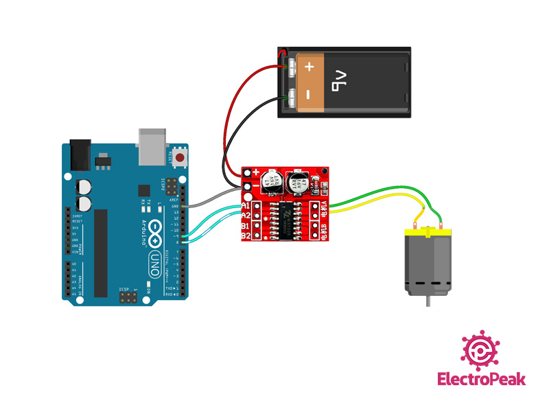
from https://electropeak.com/learn/interfacing-mx1508-motor-driver-module-with-arduino/

留言
張貼留言